Connecting TwPM to mainboard
This document describes how TwPM can be connected to the mainboard.
WARNING
The TPM header is not standardized, make sure that you're using proper pinout for your mainboard. Just because it physically looks identical (even including key that is supposed to make connection of bad TPM type impossible) doesn't mean it has the same signals on the same pins. The pinout is usually described in the mainboard's manual, refer to it before attempting to connect the module. Wrong connection may break your TPM, mainboard, or both. We do not take responsibility for potential damage caused by it. You have been warned.
Pinout for TwPM based on OrangeCrab
This is valid for TwPM built for OrangeCrab from release v0.3.0.
Pinout from official documentation:
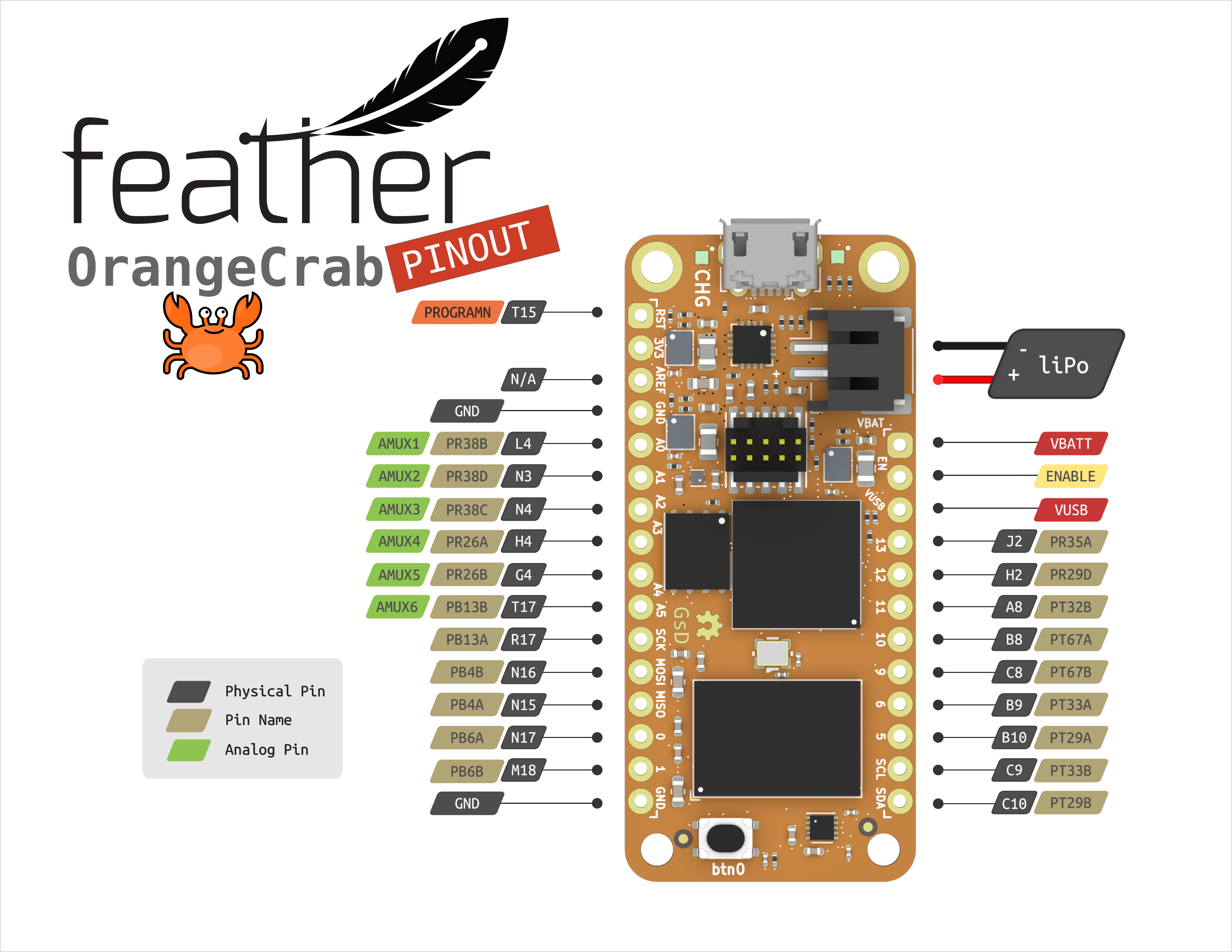
Unfortunately, there are many different labels assigned to each pin. Each of the types of identification is important to different group of people, or for different tasks. The table below maps signal names to physical pin numbers (i.e. as they are described in .lpf files, this is what FPGA tools need) and I/O numbers (i.e. what is printed on the board, you will most likely use this to find the correct pin).
In addition to signals for exchanging data with the mainboard, 3V3 and GND
must also be connected to supply power to the OrangeCrab.
If those pins need to be changed for any reason, it can be done in
orangecrab.lpf file.
Remember to change SITE of given signal to another physical pin, not only the
comment which contains I/O number. For OrangeCrab, mapping between I/O pins and
physical ports can be read from schematics.
Note that only one of the below interfaces is enabled at any given time. Switching between them requires rebuilding and flashing the new bitstream.
LPC
| Signal name | Physical Pin | I/O number |
|---|---|---|
| LCLK | H2 | 12 |
| LRESET# | J2 | 13 |
| LFRAME# | A8 | 11 |
| LAD[0] | B8 | 10 |
| LAD[1] | C8 | 9 |
| LAD[2] | B9 | 6 |
| LAD[3] | B10 | 5 |
| SERIRQ | C9 | SCL |
SPI
| Signal name | Physical Pin | I/O number |
|---|---|---|
| CLK | H2 | 12 |
| MISO | J2 | 13 |
| MOSI | A8 | 11 |
| CS_N | B8 | 10 |
| PIRQ | C9 | SCL |
Mainboard pinouts
The presented list has only mainboards that are confirmed to be valid. You are free to try it on the boards not listed below, assuming you know what you're doing.
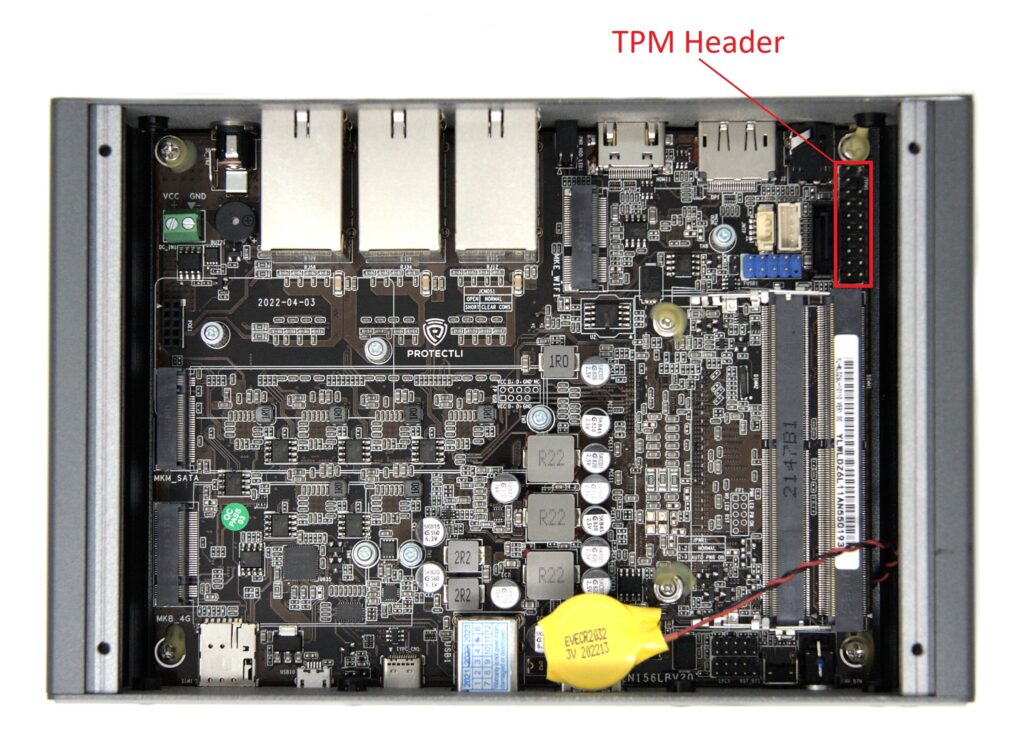
Protectli VP46xx (LPC)
Protectli platforms from VP46xx series have header compatible with TPM-01. It is 2x10 pin header, with key on pin 4. It is dangerously similar to multiple Gigabyte and Supermicro TPMs, but their layout is different so those are not compatible.
Pinout:
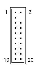
| Pin No. | Definition | Pin No. | Definition |
|---|---|---|---|
| 1 | LCLK | 2 | GND |
| 3 | LAD0 | 4 | key |
| 5 | LAD1 | 6 | NC |
| 7 | LAD2 | 8 | GND |
| 9 | LAD3 | 10 | GND |
| 11 | LFRAME# | 12 | GND |
| 13 | LRESET# | 14 | NC |
| 15 | NC | 16 | NC |
| 17 | GND | 18 | VDD (3.3V) |
| 19 | SERIRQ | 20 | NC |
Some of the NC pins are actually used for other purposes. For clarity and to
avoid making mistakes they are not marked above.
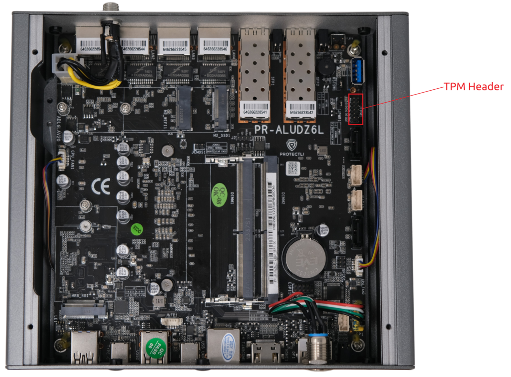
Protectli VP66xx (SPI)
Protectli platforms from VP66xx series have header compatible with TPM-02. It is 2x6 pin header, with key on pin 10, and a pitch different than OrangeCrab (2.00 mm instead of 2.54 mm), make sure you have proper wiring. The header is the same as on some of the MSI boards. Gigabyte uses rotated version of this pinout, while it looks the same, the pinout is different.
Pinout:
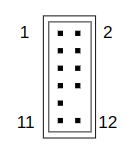
| Pin No. | Definition | Pin No. | Definition |
|---|---|---|---|
| 1 | VDD (3.3V) | 2 | CS_N |
| 3 | MISO | 4 | MOSI |
| 5 | NC | 6 | CLK |
| 7 | GND | 8 | NC |
| 9 | NC | 10 | key |
| 11 | NC | 12 | PIRQ |
Some of the NC pins are actually used for other purposes. For clarity and to
avoid making mistakes they are not marked above.